In this article, I will describe how to install and align a satellite dish on a polar mount, and explain what USALS is and why we need it. The system discussed here uses a DiSEqC H-H motor.
 First, a little theory to explain the process :). Television satellites are usually placed in geostationary orbit directly above the Earth’s equator. They orbit at the same angular speed as the Earth rotates, so each satellite appears stationary at its own orbital position to an observer on the ground.
When aligning a dish for a single satellite, our task is to obtain the strongest possible signal at the LNB output.
Aligning a polar mount is more demanding: the dish must accurately follow the geostationary orbital arc so that we can select any satellite visible from our location.
Installing the mounting bracket.
 The support on which the motorised system will be installed must be PERFECTLY VERTICAL! Even a small deviation from vertical makes accurate orbital alignment impossible. Use a spirit level or plumb line and check the support as precisely as possible in every plane.
A few words about choosing a location, bearing in mind that we are in the Northern Hemisphere. With the motor at its zero position, the dish must pointDUE SOUTH!, corresponding in our area to 30°27′ East. There must be no obstructions within 75° to the east on the left and 75° to the west on the right. Satellites at the ends of the visible arc, such as Yamal 201 at 90°E or Hispasat at 30°W, sit very low on the horizon. The dish points almost parallel to the ground, which must also be considered when choosing the location.
 The motor.
Our system uses a Strong DiSEqC motor. If you choose a different manufacturer, I strongly recommend checking its operation with DiSEqC 1.2 and USALS before installation. I have had the unfortunate experience of discovering, after painstaking alignment, that a motor did not respond correctly to receiver commands. Replacing it means dismantling the whole system :( .
The receiver.
We will control the polar mount with a ViSat VS3070CA receiver, which has performed well in these systems. It reliably supports the required motor-control protocols, has clear menus and provides enough power for the system’s components.
The dish reflector.
According to its instructions, our chosen motor can carry  a dish up to 120 cm in diameter. Rather than push that limit, we will use an 88 cm Triax reflector. These dishes collect as much signal as larger, cheaper competitors. In the author’s comparison, the result is equivalent to a 110 cm unbranded dish.
The bracket is installed and all the equipment is ready, so we can begin  assembly. Assemble the motor according to its instructions, then attach the dish bracket to the motor shaft. Two points are particularly important: the motor must be at zero on its azimuth scale, and the dish bracket must be centred precisely on the casting line along the shaft, which marks its axis.
Next, make a plumb line and attach it to the top of the dish,  on its vertical axis of symmetry. If the bracket is correctly positioned, the line will run exactly along that axis. If it does not, adjust the dish bracket on the motor shaft until they line up. The resulting assembly should look like this:
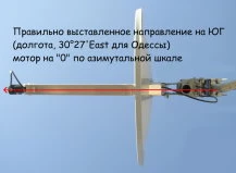
As the photograph from below shows, the system’s initial alignment follows the installation site’s meridian — 30°27′E in this example.
Next, set the elevation angle: ELEVATION = 90° − 46.3° (latitude), giving 43.7°. 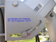
You can also find the required angle in the table supplied with the motor.
The table also gives the declination angle, which we will fine-tune during alignment.
The initial settings are now complete:
— the bracket is firmly secured and the mounting pole is perfectly vertical;
— the motor is at zero azimuth, secured to the bracket, with elevation set to 43.7°;
— the reflector is secured to the motor shaft and aligned vertically using the plumb line;
— the entire assembly points due south (30°27′E), using a compass or another method you know :).
 Now we can start tuning!
Connect the LNB to the motor, the motor to the receiver and the receiver to the TV, then turn on the power. First, align the top of the orbital arc, which lies due south. Arabsat 2B at 30.5°E would be ideal, but at the location described it could not be received even with a 180 cm dish. We therefore use its western neighbour, ASTRA 2A/2B at 28.2°E. This is 2.3° west of the top point, so we need to move the motor 2.3° west. How do we do that?
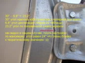
In our case it is easy: we chose components with USALS support, and this is where it helps.
On the remote, select MENU → Installation → Motor settings. For each satellite in the top row, choose USALS as the motor-control method below. Then enter your site coordinates from a map, GPS or the internet. The coordinates given for Odesa’s Television Institute on Mechnykova Street are 46°27′ North and 30°43′ East.
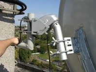
Press MENU to go back one level, then select Auto search. The satellite list is on the left. As you move through it, the motor follows the selected positions. Select ASTRA 2A/2B at 28.2°E and press OK; its cross changes to a check mark. Press Volume + to enter the transponder list and choose a transponder that is reliably received locally on a 90 cm dish, such as 11527 V in the original setup.
The signal-level and quality meters are at the bottom. We are mainly interested in the green quality bar on the right.
With the receiver and TV visible, adjust declination by moving the reflector vertically without changing the elevation already set. Find the strongest signal, then tighten the bolts while watching for any drop in quality. If the earlier steps were performed correctly, the polar mount is now aligned with the orbital arc.
To check the alignment, select and scan the end positions: Yamal 201 at 90°E and Hispasat 1C at 30°W. Allow time for the motor to move between positions. Its speed depends on polarisation; it moves noticeably faster with horizontal polarisation.
P.S.
If the alignment did not work… :(
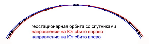
 The diagrams below show two possible alignment errors: an incorrect southward direction or an incorrect elevation angle.
In the first case, the arc is shifted left or right: satellites lie above the dish’s path on one side of south and below it on the other. The diagram indicates the correction needed. Return to the reference satellite at 28.2°E and rotate the motor on its bracket by 1–2°, for example anticlockwise. Then rotate the dish on the shaft in the opposite direction to regain maximum signal. Lightly tighten the brackets and check the ends of the arc. If the result is worse, you chose the wrong direction.
The second case is an incorrect elevation setting. If elevation is too low and you compensate at the reference satellite using declination, satellites at both ends of the arc appear above the dish’s path; the opposite error sends them below it. In the correction described here, if both ends fall below the path, reduce elevation and increase declination while maintaining maximum signal. If both ends rise above it, increase elevation and reduce declination. 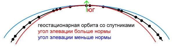
If both errors occur together, it may be time to call a specialist. Satellite TV alignment can be a demanding business… :)))